Introduction
If you have ever worked on an electric motor, there is a pretty high chance you have come across Fleming’s Left Hand Rule. This rule is named after an electrical engineer and physicist named Sir John Ambrose Fleming.
He was known as the inventor of the vacuum tube and the one who established something called the right hand rule in physics during the 19th century. So now that we know a little about Fleming, what exactly is Fleming’s Left Hand Rule?
Fleming’s left-hand rule is a simple mnemonic that is used to determine the direction of the induced current in an electric motor. The rule states that if you extend the thumb, forefinger, and middle finger of your left hand so that they are mutually at right angles, then the direction in which the thumb points is the direction of the current that is induced in the motor. The forefinger indicates the direction of the magnetic field, and the middle finger indicates the direction of motion.
In more detail, when a conductor is placed in a magnetic field, an electromotive force (EMF) is induced in the conductor that is proportional to the rate of change of the magnetic flux through the conductor. This induced EMF results in an induced current flowing in the conductor. The direction of the induced current is determined by the direction of the EMF, which is given by Lenz’s Law. Lenz’s Law states that the induced current will be in such a direction that the magnetic field it creates will oppose the change in the magnetic field that produced it.
In summary, Fleming’s left-hand rule helps to determine the direction of the induced current in a motor, by showing the direction of thumb, forefinger and middle finger as the direction of current, magnetic field and motion respectively.
Well it is used to accurately find the direction of force or motion of a conductor within an electric motor in a simple way. This rule can only be applied though when the magnetic field direction and the current direction are already known, so it can’t be used for stepper motors, brushless DC motors, servo motors, or brushless motors. To get more background information we will first start with what a motor is.
Table of contents
What is a Motor?
The word “motor” refers to any power supply unit that generates motion. There are several different types of motor power supply units. Some common applications of electric motors exist within electric vehicles including electric cars and electric trains will have a motor known as an electric motor, which converts kinetic energy into electrical energy. The first person to invent a working electric motor was William Sturgeon.
Amusement machines also tend to use electric motors as they are a type of electrical machine. This is different from a normal car which has an engine instead of a motor. Scientifically speaking, the electric motor is a unit used to convert electric power into motive energy or electrical energy into mechanical energy. This is different from an engine which runs on combustion. The diagram below highlights how an electric motor works in terms of energy.
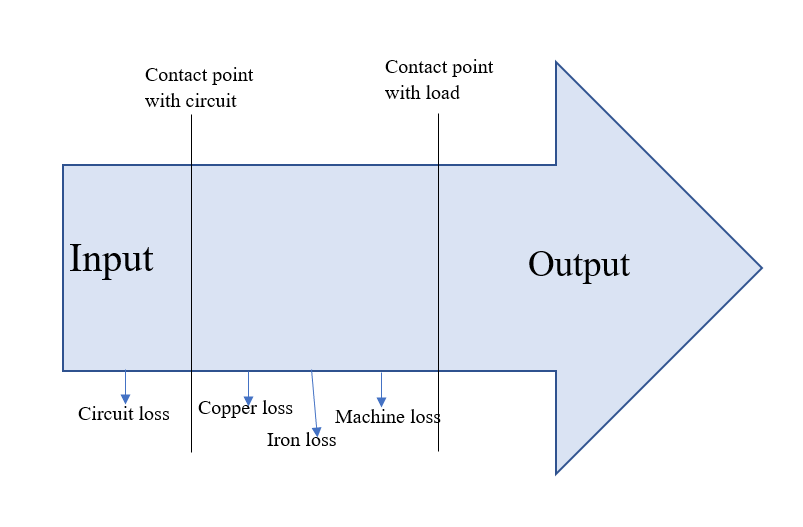
The left end of the arrow represents the electrical input and the right end the mechanical output respectively. Electrical input may be simply shortened to read input, and mechanical output can be simply shortened to output. The output should be less than terminal voltage otherwise the circuit will overload. The average voltage should be anywhere from 1.5 volts to 100 volts. During the energy conversion process, some input becomes heat instead of motive energy. This is known as loss. Some different types of loss can be seen in the image.
Keep in mind an electric motor converts electric power into energy, but how is this actually achieved? This is achieved by the principle of electromagnetic induction. Electromagnetic induction is the principle that a current carrying conductor, when placed in a magnetic field that contains a north of and south pole, with adequate magnetic flux density, it will have a force exerted on the conductor proportional to the current flowing and the strength of the magnetic field. The basic principles of electromagnetic induction were discovered in the early 1800’s by Oersted, Gauss and Faraday.
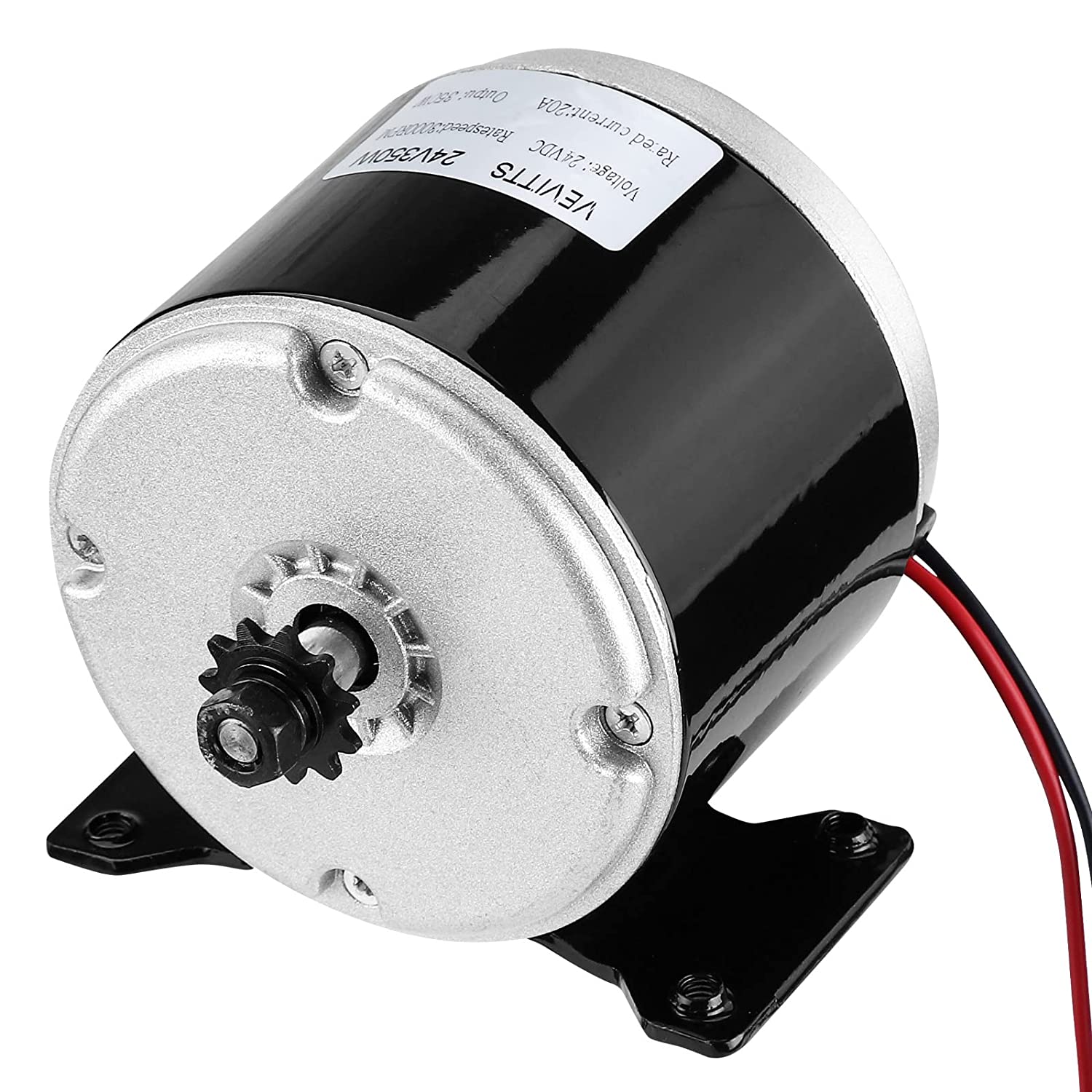
However, it was Tesla who was able to take motor technology to the next level in the late 1800’s and revamped the manufacture of motors as well. There are six essential components to a basic electric motor, these are the fan, windings, commutator, field poles, shaft, and coil geometry. An image of a basic electric motor can be seen below.
Fleming’s Left-hand Rule
If a current carrying conductor placed in a magnetic field, it experiences a force due to the magnetic field. On the other hand, if a conductor moved in a magnetic field, an electromagnetic field gets induced across the conductor. John Ambrose Fleming introduced two rules to determine the direction of motion (in motors) or the direction of induced current (in generators). The rules are called as Fleming’s left hand rule for motors, and Fleming’s right hand rule, which is used for generators.
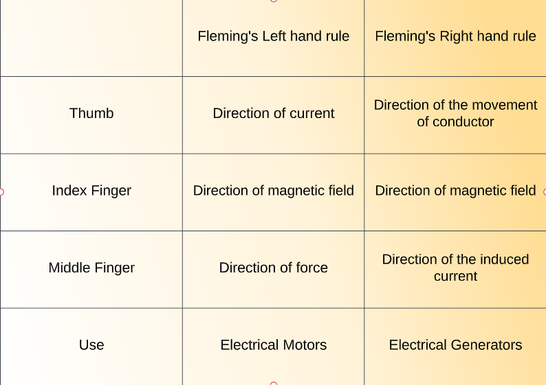
Whenever a conventional current carrying conductor is placed in a magnetic field, with an adequate magnetic flux density, the conventional current carrying conductor experiences a force which is perpendicular to both the magnetic field and the direction of current. A current refers to a flow of electrons. According to Fleming’s left hand rule, if the thumb, fore-finger and middle finger of the left hand are stretched to be perpendicular to each other as shown in the illustration below, and if the fore finger represents the direction of magnetic field and magnetic flux density, the middle finger represents the direction of an electric current, then the thumb represents the motor direction of force. Fleming’s left hand rule is applicable for motor currents and electric motors in general.
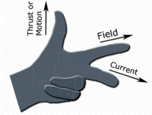
Image taken from Wikipedia
Fleming’s right hand rule on the other hand is applicable for electrical generators. As per Faraday’s law of electromagnetic reduction, whenever a conductor is forcefully moved in an electromagnetic field, an emf gets induced across the conductor. If the conventional current carrying conductor is provided a closed circuit coil path, then the induced emf causes a current to flow.
According to the Fleming’s right hand rule, the thumb, fore finger and middle finger of the right hand are stretched to be perpendicular to each other as shown in the illustration at right, and if the thumb represents the direction of the movement of conductor, fore-finger represents direction of the magnetic field, then the middle finger represents direction of the induced current.
If you are ever confused just remember that the thumb represents the direction of thrust on the conductor (force on the conductor). The fore finger represents the direction of the magnetic field. Finally, the center finger (middle finger) is used to show which way the electric current flows. Fleming’s right hand rule can be seen visually below.
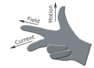
Image taken from Wikipedia
The table below summarizes the difference between the two in a simple to understand way.
Coreless Motor Rotation Principle
Some motors can be coreless, such as a coreless DC motor. A typical DC motor, as opposed to AC induction motors, stepper motors, and other simple motors, consists of an outer stator, typically made of either a permanent magnet or electromagnetic windings, and an inner rotor made of iron laminations with coil windings that turn half way. A segmented commutator and brushes control the sequence in which the rotor windings are energized, to produce continuous direction of rotation.
In a DC motor, the input electrical energy is the direct current which is transformed into the mechanical rotation, it moves north to south. The principle of operation in a coreless DC motor is different. In a coreless DC motor does away with the laminated iron core in the rotor. Instead, the rotor windings are wound in a skewed, or honeycomb, fashion to form a self-supporting hollow cylinder. Since there is no iron core to support the windings, they are often held together with epoxy. The construction of a coreless DC motor provides several advantages over a traditional, iron core DC motor. Some are listed below.
- First, the elimination of iron significantly reduces the mass and inertia of the rotor, so very rapid acceleration and deceleration rates are possible.
- No iron also means no iron losses, giving coreless designs significantly higher efficiencies than a traditional DC motor.
- The coreless design also reduces winding inductance, so sparking between the brushes and commutator is reduced, increasing motor life and reducing electromagnetic interference also known as EMI.
- Motor cogging, which is an issue in traditional DC motors due to the magnetic interaction of the permanent magnets and the iron lamination’s, is also eliminated, since there are no laminations in the ironless design.
- Torque ripple is extremely low, which provides very smooth motor rotation with minimal vibration and noise.
Coreless designs are an especially good solution for battery-powered devices because they draw extremely low current at no-load conditions. A coreless DC motor is used extensively in medical applications, including prosthetics, small pumps (such as insulin pumps), laboratory equipment, and X-ray machines. Their ability to handle fast, dynamic moves also makes them ideal for use in robotic applications. An image of a coreless DC motor can be seen below.

Image taken from Amazon
Applications of Fleming’s Left Hand Rule in Motors and Robotics
One of the most common and well-known applications of Fleming’s left-hand rule can be seen in the working of an electric motor. To understand how Fleming’s Left-Hand Rule is applied first we need to understand how an electric motor actually works. When an electrical current is passed through a conductor, it generates a cylindrical magnetic field around the conductor. If an external magnetic field is brought close to the current-carrying conductor, the magnetic field and the electromagnetic field interact. This interaction between current and magnetic fields will produce a physical force. To calculate the direction of this force, we use this rule.
If the middle finger of the left hand gives the direction of the electric current, the forefinger represents the direction of an external magnetic field, then the thumb of our left hand will point in the direction of the force. In a standard DC electric motor as opposed to a brushless DC motor, the electromagnetic field interacts with the magnetic field generated by the permanent magnets, and due to this interaction, a physical force is generated. Using this rule, we can determine the rotation direction of this force and the direction of the motor’s motion. It can be used to understand the motion in any of the multitude of different types of electric motors in a simplified way.
Fleming’s left-hand rule is important because it provides a simple and accurate way of finding the direction of the force experienced by a current-carrying conductor in a magnetic field, given that you know the direction of both the current and the magnetic field. We saw the importance of this rule in the use case of an electric motor, where we could easily identify the direction in which the force acts on the arms of an electric motor. Considering that the workings of the electric motor are well-understood in part due to Fleming’s left-hand rule, we can conclude that Fleming’s left-hand rule is, although indirectly, important in everyday life as well as most mechanical movement today is done using electric motors.
Conclusion
Fleming’s Left-Hand Rule is an important concept to understand when working with electric motors. Fleming’s left-hand rule is particularly suitable to find the direction of force on a current conductor when it is placed in a magnetic field. It is also very simple to use, only requiring your left hand and nothing else. Even though it is simple it is still incredibly accurate. We hope that you have learned more about Fleming’s Left-Hand Rule and some general advice on motors. Thank you for reading this article.
